



Important: Never order dismantling joints only by DN nominal size. Mismatched flange, adjustment range or chamber space will lead to leakage & construction delay. Always check valve‑chamber drawings.
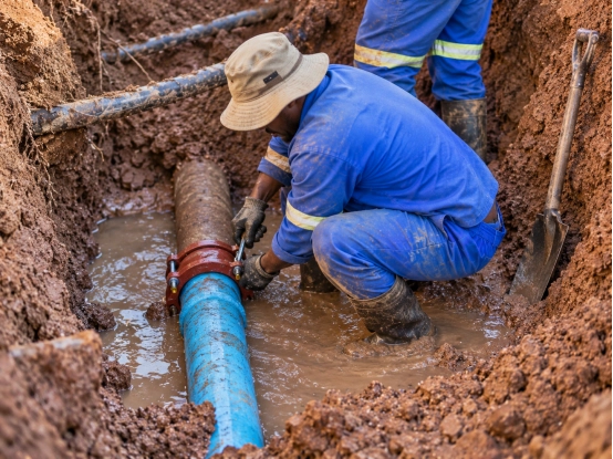
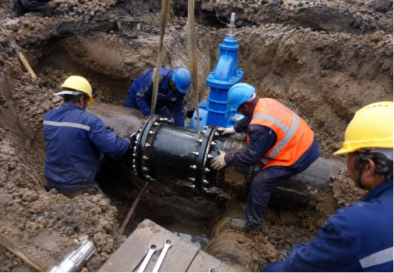
A 560 mm potable water pipeline rehabilitation project in South Africa shows why a dismantling joint must be selected from the valve chamber drawing rather than from nominal diameter alone. Its isolation chamber layout places a 600 mm dismantling joint beside a 600 mm butterfly valve, creating axial adjustment for installation and later valve removal.
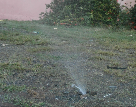
For an African water utility, contractor or procurement team, the joint must match the flange drilling, pressure class, adjustment range, coating, gasket and maintenance space specified for that exact chamber. One mismatch can delay installation or create a leak path after commissioning.
Start With the Dismantling Joint Drawing
A dismantling joint drawing should establish the dimensions and interfaces that control installation. Check the nominal diameter, overall installed length, available axial adjustment, flange outside diameter, pitch circle diameter, number and diameter of bolt holes, and the size and number of tie rods. These values should be compared with the valve schedule and the adjoining pipework, not reviewed in isolation.
Some drawings treat piping, butterfly valves, and connections as a single unit. A dimensionally correct joint can still be impossible to maintain if the chamber wall prevents bolt withdrawal or leaves no room to shorten the telescopic section.
Attach the approved chamber drawing to the RFQ. If the design is incomplete, state the pipe DN, valve face to face dimension, installation gap and maximum joint length. A wider gasket range cannot correct missing civil dimensions.
Match DN, Pressure Rating and Flange Drilling
DN alone cannot guarantee compatibility. Confirm flange standard (EN1092 / ANSI). Pressure rating must cover working pressure plus water surge pressure. Conflex DI dismantling joint: DN50‑DN2000, PN10/16/25/40, supports EN1092 & ANSI flange drilling.
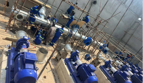
Pressure selection should cover normal operation and credible surge pressure. Pump starts, rapid valve closure and elevation changes can raise transient pressure. The joint, valve, bolts and adjacent flanges must share a compatible rating. A separate South African municipal groundwater upgrade specification illustrates this coordination by specifying 150 mm dismantling joints, valves and flow control equipment at PN16 within the same chamber schedule.
Conflex’s DI dismantling joint is available from DN50 to DN2000 with PN10, PN16, PN25 and PN40 options. Its published range includes EN 1092 and ANSI flange drilling. The correct combination still needs to be stated on the purchase order because these options are not interchangeable.
Specify Adjustment Without Treating It as Expansion Capacity
The telescopic movement creates installation and removal space. It is not a substitute for an expansion joint and should not absorb continuous thermal or ground movement. In a valve chamber, it closes the assembly to its operating length and later shortens enough for equipment removal.
The Conflex dual-flange design has an adjustment range of approximately 50 mm. Sufficiency depends on valve geometry, gasket arrangement, lifting method and whether the joint can retract without striking the chamber.
Settlement, thermal movement and vibration require separate engineering. The difference between a dismantling joint and a flange adaptor should also be clear: a flange adaptor connects a plain-ended pipe to flanged equipment, while a dismantling joint sits between flanged components and provides controlled axial adjustment.

Check Restraint, Gaskets and Corrosion Protection
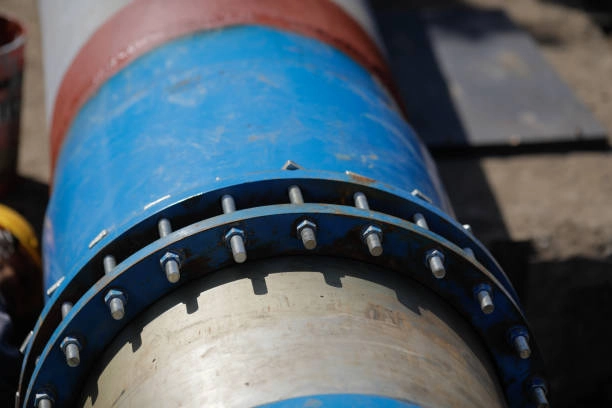
Tie rods are structural parts, not shipping accessories. They transfer axial thrust through the assembly and prevent the telescopic joint from extending under pressure. Supplier data should identify their quantity, grade, coating and tightening arrangement.
For potable water, gasket and coating requirements should follow project approvals. EPDM is commonly selected for water, while NBR suits some oil-related services. Fusion-bonded epoxy and protected fasteners are valuable in humid chambers, but coating thickness and acceptance tests belong in the specification.
conflex offers EPDM, SBR, and NBR gasket options, ductile iron components conforming to EN 1563, fusion-bonded epoxy protection, and drinking water applications. Buyers should request the exact material schedule and approval documents for the proposed configuration instead of assuming every option applies to every size.
Plan the Dismantling Joint Installation Before Delivery
A sound installation begins before delivery. Verify flange faces, bore, pressure class and joint condition, then confirm that pipe supports carry the assembly. Position the joint between aligned flanges and bolt both sides before final tightening of the sealing gland and tie rods.
Tighten bolts gradually in a cross pattern to the manufacturer’s torque. Uneven compression, debris at the seal, damaged flange coating and insufficient support can all produce leakage.
The full dismantling joint installation guidance explains the sequence for checking the product, matching the flanges, adjusting the joint, fitting the pull rods and rechecking torque. Project-specific method statements should add lifting, confined-space and pressure-test controls required by the local utility.
What African Water-Project Buyers Should Put in the RFQ
Include below information in RFQ:
- Pipeline & valve DN
- Design & test pressure
- Flange standard
- Required adjustment range
- Material, gasket and coating requirements
- Service medium & valve‑chamber drawing
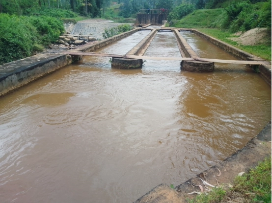
The Conflex website documents the Karonga water-supply upgrading project in Malawi, involving uPVC and ductile-iron pipelines plus treatment, storage and pumping infrastructure.
Choose the Joint as Part of the Valve-Chamber Assembly
A dismantling joint should be selected as part of a restrained, supported and maintainable valve-chamber assembly. Start with the approved drawing, then match pressure, flange drilling, adjustment, materials and installation access. If only one rule is remembered, it should be this: do not release the purchase order until the joint drawing has been checked against the actual valve and chamber dimensions.
Send Conflex the pipeline drawing, valve data sheet, DN, PN, flange standard and service medium to confirm a suitable dismantling joint configuration for the project.
常见问题解答
Q: What is a dismantling joint used for in a valve chamber?
A dismantling joint provides controlled axial adjustment between flanged components. It helps installers fit a valve, pump or flow meter and later creates clearance for removal without cutting the pipeline.
Q: How much adjustment does a dismantling joint provide?
The adjustment depends on the manufacturer and model. Conflex publishes approximately 50 mm for its double-flanged design, but the selected size and approved drawing should be checked before procurement.
Q: Is a dismantling joint the same as an expansion joint?
No. A dismantling joint provides installation and maintenance adjustment and is normally restrained with tie rods. An expansion joint is designed to accommodate defined movement such as thermal expansion, vibration or displacement.
Q: Which details are required when ordering a dismantling joint?
Provide DN, pressure class, flange drilling, mating-equipment details, required adjustment, body and fastener materials, gasket compound, coating specification, service medium and the approved valve-chamber drawing.